
The Serial Peripheral Interface (SPI) protocol is a widely used communication standard that facilitates data exchange between microcontrollers and peripheral devices such as sensors, memory modules, displays, and other digital systems. Developed by Motorola in the mid-1980s, SPI has become a standard for high-speed, full-duplex communication in embedded systems and electronics.
What is SPI?
SPI is a synchronous serial communication protocol that uses a master-slave architecture to transfer data. Unlike asynchronous protocols, SPI relies on a shared clock signal to synchronize the communication between devices, ensuring that both the transmitter and receiver are aligned in terms of timing.
SPI is widely used due to its simplicity, speed, and versatility in supporting multiple devices on the same bus. In an SPI system, the devices are typically configured in a master-slave arrangement, where one master device controls the communication, while the slave devices respond to commands from the master.
Key Features of SPI
- Full-Duplex Communication: SPI allows simultaneous transmission and reception of data. This enables fast data transfer, as both devices can send and receive data at the same time.
- Clock-Based Synchronization: Data transfer is synchronized by a clock signal (SCLK), ensuring that both sender and receiver are aligned in terms of timing.
- Multiple Devices: SPI can support multiple slave devices on a single bus, with the master device selecting which slave to communicate with using a unique chip-select (CS) line for each slave.
- High Speed: SPI is capable of very high data transfer rates compared to other serial communication protocols like UART and I2C.
- Simple Wiring: SPI requires a minimal number of wires—at least four—for communication, making it simple to implement in hardware.
SPI Bus Lines
A standard SPI communication setup uses four main signals:
- MOSI (Master Out Slave In): This line carries data from the master device to the slave device(s). The data is shifted out of the master and into the slave.
- MISO (Master In Slave Out): This line carries data from the slave device back to the master. The data is shifted out of the slave and into the master.
- SCK (Serial Clock): This is the clock signal generated by the master device. The clock pulse synchronizes the timing of the data transfer between the master and slave devices.
- CS (Chip Select or Slave Select): This signal is used to select the active slave device for communication. When the master wants to communicate with a specific slave, it pulls the corresponding CS line low (active low). Multiple slave devices can share the same SPI bus, but each will have a separate CS line to be selected.
SPI Communication Process
The data transfer in SPI involves several steps:
- Device Selection: The master selects the slave device it wants to communicate with by asserting the corresponding CS line. The other slaves’ CS lines remain high (inactive).
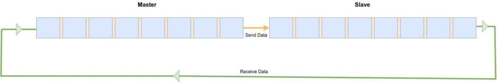
- Data Transfer: The master generates a clock signal (SCK), and data is transferred serially along the MOSI and MISO lines. On each clock pulse, one bit of data is transferred from the master to the slave (via MOSI) and from the slave to the master (via MISO).
- Data Synchronization: Both the master and slave devices synchronize data transfer based on the clock signal. One clock cycle corresponds to the transfer of one bit of data.
- End of Communication: The communication ends when the master deasserts the CS line, which tells the slave that the transaction is complete.
SPI Modes
SPI communication can be configured in several modes based on the clock polarity (CPOL) and clock phase (CPHA). These settings determine when data is sampled relative to the clock signal.
- CPOL: Clock polarity defines the idle state of the clock signal. If CPOL = 0, the clock is low when idle; if CPOL = 1, the clock is high when idle.
- CPHA: Clock phase defines when data is sampled relative to the clock signal. If CPHA = 0, data is sampled on the rising edge of the clock; if CPHA = 1, data is sampled on the falling edge of the clock.
There are four SPI modes based on these two parameters:
- Mode 0: CPOL = 0, CPHA = 0
- Mode 1: CPOL = 0, CPHA = 1
- Mode 2: CPOL = 1, CPHA = 0
- Mode 3: CPOL = 1, CPHA = 1
The master and slave devices must be configured to use the same SPI mode to ensure proper communication.
Maximum Data Rates
The maximum data rate (or speed) of an SPI (Serial Peripheral Interface) communication depends on several factors, including the following:
- Hardware Capability: The microcontroller’s SPI hardware can typically support a maximum clock frequency. The actual maximum data rate is limited by the hardware clock speed, which is the frequency of the SCK (Serial Clock) signal.
- Quality of Connections: Long wires or poor-quality connections can introduce noise and signal degradation, which can limit the maximum data rate.
- Peripheral Limitations: The slave devices connected to the SPI bus also need to support the same high data rate as the master device. If the peripheral is slow, it can limit the maximum achievable data rate.
Implementing SPI Protocol using Bit-Banging on Arduino
Bit-banging is a technique where you manually control the timing of signals in software, instead of relying on hardware peripherals like the SPI hardware module in an Arduino. This is a useful approach when you need full control over the communication process or if the hardware doesn’t have a dedicated SPI interface. Bit-banging SPI involves controlling the clock (SCK), data out (MOSI), and data in (MISO) pins directly in code.
In this example, we’ll create an implementation of the SPI protocol using bit-banging on an Arduino. We will assume a basic scenario where we send data from the master (Arduino) to the slave (such as an LED or another Arduino) and possibly receive data back from the slave as well.
// Pin definitions for the SPI signals
#define MOSI 11
#define MISO 12
#define SCK  13
#define SS   10

void setup() {
  // Initialize SPI pins
  pinMode(MOSI, OUTPUT);   // Master out
  pinMode(MISO, INPUT);    // Master in (slave's data to master)
  pinMode(SCK, OUTPUT);    // Clock signal
  pinMode(SS, OUTPUT);     // Chip select for SPI

  // Set SS pin high to deselect slave
  digitalWrite(SS, HIGH);
}

void loop() {
  byte dataToSend = 0x55;  // Example data to send (0x55)
  byte receivedData = 0;    // Variable to store received data

  // Send and receive data via SPI (bit-banging)
  receivedData = spiTransfer(dataToSend);

  // You can use receivedData for further processing if needed
  delay(1000);  // Delay between transfers
}

// SPI transfer using bit-banging
byte spiTransfer(byte data) {
  byte receivedData = 0;

  // Loop through each bit (8 bits in total)
  for (int i = 7; i >= 0; i--) {
    // Set the MOSI line (send bit) based on the current data bit
    if (data & (1 << i)) {
      digitalWrite(MOSI, HIGH);  // Set MOSI to 1
    } else {
      digitalWrite(MOSI, LOW);   // Set MOSI to 0
    }

    // Create a clock pulse (high then low)
    digitalWrite(SCK, HIGH);  // Set clock high
    delayMicroseconds(10);    // Small delay for stable clock signal
    digitalWrite(SCK, LOW);   // Set clock low
    delayMicroseconds(10);    // Small delay for stable clock signal

    // Read data from MISO (Slave to Master) on the rising edge of the clock
    receivedData |= (digitalRead(MISO) << i);
  }

  return receivedData;
}
Advantages of SPI
- Speed: SPI can operate at much higher speeds compared to other protocols like I2C or UART. This makes it ideal for applications that require high-speed data transfer.
- Simplicity: The protocol is simple to implement with a small number of signals (MOSI, MISO, SCK, and CS). This simplicity helps reduce system complexity.
- Full-Duplex Communication: Both sending and receiving data simultaneously improves the efficiency of the communication.
- Flexibility: SPI supports multiple slave devices, and devices can be added or removed from the bus without disrupting communication.
Disadvantages of SPI
- Limited Distance: SPI is not designed for long-distance communication. The bus length should typically be kept short (a few meters at most) to maintain signal integrity.
- Pin Count: While SPI requires fewer pins than some other communication protocols, it does require a dedicated CS line for each slave device. This increases the pin count as the number of slaves grows.
- No Acknowledgement: Unlike protocols like I2C, SPI does not include any form of acknowledgment or error-checking in the protocol itself. This means that higher-level protocols or hardware error detection mechanisms are necessary to ensure data integrity.
Conclusion
The SPI protocol is an essential tool for high-speed data transfer in embedded systems and microcontroller-based designs. Its simplicity, flexibility, and speed make it ideal for applications requiring fast communication with low overhead. Although it has limitations in terms of distance and scalability, SPI remains a dominant choice in many systems that require fast, reliable data exchange between devices. Understanding SPI’s key features, operational modes, and typical use cases can help engineers design efficient systems that leverage the full capabilities of this versatile protocol.