
A voltage divider is one of the most essential and straightforward concepts in electronics. It’s a simple circuit that allows you to reduce or “divide” the voltage from a source to a lower, more manageable level. Whether you’re working with microcontrollers, sensors, or analog circuits, voltage dividers are often used to adjust voltage levels for various components or to create reference voltages.
In this article, we will explore what voltage dividers are, how they work, the formula for calculating output voltage, and provide practical applications of voltage dividers in everyday electronics projects.
What is a Voltage Divider?
A voltage divider is a passive circuit consisting of two or more resistors connected in series. It works on the principle of Ohm’s Law and the concept of resistance to divide the total input voltage into smaller, proportional voltages across the resistors.
The key idea is that the voltage drop across each resistor in the series is proportional to its resistance. By selecting the appropriate resistor values, you can “tap” a desired voltage from between the resistors.
Basic Voltage Divider Circuit
The simplest form of a voltage divider consists of two resistors, R1 and R2 connected in series, with the input voltage Vin applied across the combination. The output voltage Vout s taken from the junction between the two resistors.
Here’s a diagram of the basic voltage divider circuit:
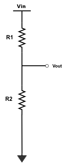
- Vin: The total input voltage applied across the series resistors
- Vout: The voltage that we measure across resistor R2 , which is the output voltage
- R1 and R2 : The resistors that divide the voltage.
How Does a Voltage Divider Work?
The voltage divider works by exploiting the relationship between the resistances in the series circuit. When current flows through a series circuit, it experiences a voltage drop across each resistor. The amount of voltage drop across each resistor is proportional to its resistance relative to the total resistance.
According to Ohm’s Law:
$$V\;=\;\;I\;\times\;R$$
Where:
- V is the voltage across a component,
- I is the current passing through the component,
- R is the resistance of the component.
Since the resistors are in series, the current through both R1 and R2 is the same However, the voltage drop across each resistor will be different, depending on the ratio of their resistances.
Formula for Output Voltage
The output voltage Vout , is calculated using the following formula:
$$Vout=\;\;Vin\;\times\;\frac{R2}{R1\;+R2}$$
Where:
- Vin : is the total input voltage across the resistors.
- R1 : is the resistance of the first resistor.
- R2 : is the resistance of the second resistor.
- Vout: is the voltage measured across R2
This equation shows that the output voltage depends on the ratio of the resistances R1 and R2 as well as the input voltage .
Example Calculation
Let’s work through an example to see how this formula works in practice.
Given:
- Input voltage Vin = 12V
- Resistor R1 = 3Kohm
- Resistor R2 = 2Kohm
We want to find the output voltage Vout.
Using the formula:
$$Vout=\;\;12V\;\times\;\frac{2k}{3K\;+2K}\;=\;4.8V$$
So, the output voltage across resistor R2 is 4.8V.
Practical Applications of Voltage Dividers
Voltage dividers are widely used in various applications. Here are some common scenarios where voltage dividers are used:
- Adjusting Voltage Levels : Voltage dividers are often used to scale down a higher voltage to a lower voltage. For example, if you’re using a 12V power supply but need a 5V reference voltage for a microcontroller or sensor, a voltage divider can easily provide the necessary output voltage.
- Sensor Interface : Some sensors (e.g., temperature sensors, photoresistors, or potentiometers) provide an analog output that needs to be scaled or conditioned before being read by a microcontroller’s analog-to-digital converter (ADC). Voltage dividers can be used to create the required voltage level for accurate measurement.
- Creating a Reference Voltage : A voltage divider is often used to create a reference voltage in a circuit. For example, you can generate a reference voltage to compare against another signal in an operational amplifier circuit or voltage comparator.
- Signal Conditioning : Voltage dividers can be used to scale down a signal to a suitable level for processing by other components. For instance, if a signal is too strong for an ADC input or if a sensor needs to operate within a specific voltage range, a voltage divider can be used to reduce the signal.
- Biasing in Transistor Circuits: Voltage dividers are often used in transistor amplifier circuits to set the biasing point of the transistor. By selecting appropriate resistor values, the voltage divider can provide a stable DC voltage to the base of the transistor, which ensures the transistor operates in the desired region.
Limitations and Considerations
While voltage dividers are simple and useful, there are a few important limitations and considerations to keep in mind:
Current Limitation: The output voltage from a voltage divider is heavily dependent on the load connected to it. If the load resistance is too low, it will draw significant current, altering the voltage divider’s output. To mitigate this, the impedance of the voltage divider (the combined resistance of R1 and R2 should be much higher than the load resistance.
Power Dissipation : The resistors in a voltage divider dissipate power, and depending on the values of the resistors and the input voltage, the power dissipation could become significant. If large resistors are used, this can limit the current through the circuit but might result in inefficient power usage.
Accuracy Issues : Voltage dividers may not be suitable for circuits that require highly stable or precise voltage levels, as temperature variations and resistor tolerances can affect the accuracy of the output voltage.
Conclusion
The voltage divider is a simple yet powerful tool in electronics, enabling the adjustment of voltage levels in a circuit. With just two resistors, you can scale down a voltage to meet the needs of your components, create reference voltages, or condition signals for processing. Understanding the voltage divider principle is essential for anyone working in electronics, as it forms the basis for many more advanced concepts and circuits.
Remember that while voltage dividers are incredibly useful, they have limitations when it comes to current handling, power dissipation, and accuracy. For more demanding applications, other methods like regulated power supplies or voltage references may be more suitable. Nonetheless, the voltage divider remains one of the most fundamental and widely used circuits in the world of electronics.