

In the realm of electronics and embedded systems, the ability to convert analog signals into digital data is crucial. This process is facilitated by devices known as Analog to Digital Converters (ADCs). Understanding how these converters work and how to implement them can open up a world of possibilities in data acquisition and processing.
Analog vs. Digital Signals
Analog Signals
Analog signals are continuous waveforms that represent information through varying physical quantities, such as voltage or current. They can take on an infinite number of values within a given range, making them ideal for capturing the nuances of natural phenomena, such as sound, light, and temperature. For instance, the sound waves produced by a musical instrument can be represented as an analog signal, preserving all the subtleties of the performance.
Digital Signals
In contrast, digital signals represent information using discrete values, typically in binary form (0s and 1s). This discretization allows for easier processing, storage, and transmission of data. Digital signals are less susceptible to noise and interference, making them more reliable for modern communication systems. For example, a digital audio file compresses the original analog sound into a series of binary numbers, enabling efficient storage and playback on digital devices.
Importance of Analog to Digital Conversion
The transition from analog to digital signals is facilitated by a process called Analog to Digital Conversion (ADC). This process is vital for several reasons:
- Improved Accuracy and Quality: ADC allows for the precise representation of analog signals, capturing details that might be lost in analog transmission due to noise or distortion.
- Storage and Processing: Digital signals can be easily stored, manipulated, and transmitted over long distances without degradation. This capability is essential in various applications, from audio and video streaming to telecommunications and data analysis.
- Compatibility with Modern Technology: As technology advances, digital systems have become the standard for most applications. ADC enables the integration of analog devices into digital ecosystems, allowing for seamless interaction between old and new technologies.
- Enhanced Security: Digital signals can be encrypted and compressed, providing added security and efficiency in data transmission.
- Versatility: Digital systems are adaptable and can be easily modified or upgraded, making them ideal for evolving technology landscapes.
What is an Analog to Digital Converter?
An Analog to Digital Converter is an electronic device that transforms an analog signal—such as sound, light, temperature, or pressure—into a digital signal that can be understood by a computer. The primary function of an ADC is to sample an analog input signal and convert it into a series of binary numbers representing the amplitude of the signal at discrete intervals.
The Conversion Process:
The conversion process involves several key steps:
- Sampling: The ADC samples the continuous analog signal at regular intervals. The rate at which the signal is sampled is known as the sampling rate or sampling frequency. According to the Nyquist theorem, to accurately reconstruct a signal, it must be sampled at least twice the highest frequency present in the signal.
- Quantization: After sampling, the next step is quantization, where the sampled values are approximated to the nearest value within a predefined range. This process introduces a small error known as quantization noise, which can affect the overall fidelity of the signal.
- Encoding: Finally, the quantized values are encoded into binary form. This typically involves converting the quantized values into binary code, allowing them to be processed, stored, or transmitted by digital systems.
Types of Analog to Digital Converters
ADCs come in various types, each suited for specific applications:
- Successive Approximation Register (SAR) ADC: This type uses a binary search algorithm to convert the analog signal into a digital value. SAR ADCs are popular for their speed and accuracy, making them suitable for applications like data acquisition systems.
- Sigma-Delta ADC: These converters use oversampling and noise shaping techniques to achieve high resolution. Sigma-delta ADCs are widely used in audio applications due to their excellent performance in converting low-frequency signals.
- Flash ADC: Known for their high speed, flash ADCs use a series of comparators to instantly convert an input signal into a digital value. They are ideal for applications requiring rapid sampling, such as oscilloscopes and high-frequency data capture.
- Pipeline ADC: These converters break the conversion process into several stages, allowing for high speed and moderate resolution. Pipeline ADCs are commonly used in video processing and communications.
Key Characteristics of ADCs:
- Resolution: The number of bits used to represent the analog signal. For instance, a 10-bit ADC can represent 1024 different values.
- Sampling Rate: The frequency at which the analog signal is sampled. Higher rates allow for more accurate representations of rapidly changing signals.
- Input Range: The range of voltages that can be accurately converted by the ADC.
- Linearity: The degree to which the output signal is proportional to the input signal.
ADC in arduino uno
The Arduino Uno features the AVR-based ATmega328 microcontroller, which boasts a 10-bit resolution for analog-to-digital conversion. This ADC can handle input voltages ranging from 0 to 5 volts and achieves a sampling rate of approximately 9,600 samples per second. Additionally, the microcontroller supports six analog input channels and offers an internal reference voltage of 1.1 volts, enhancing measurement accuracy for various applications.
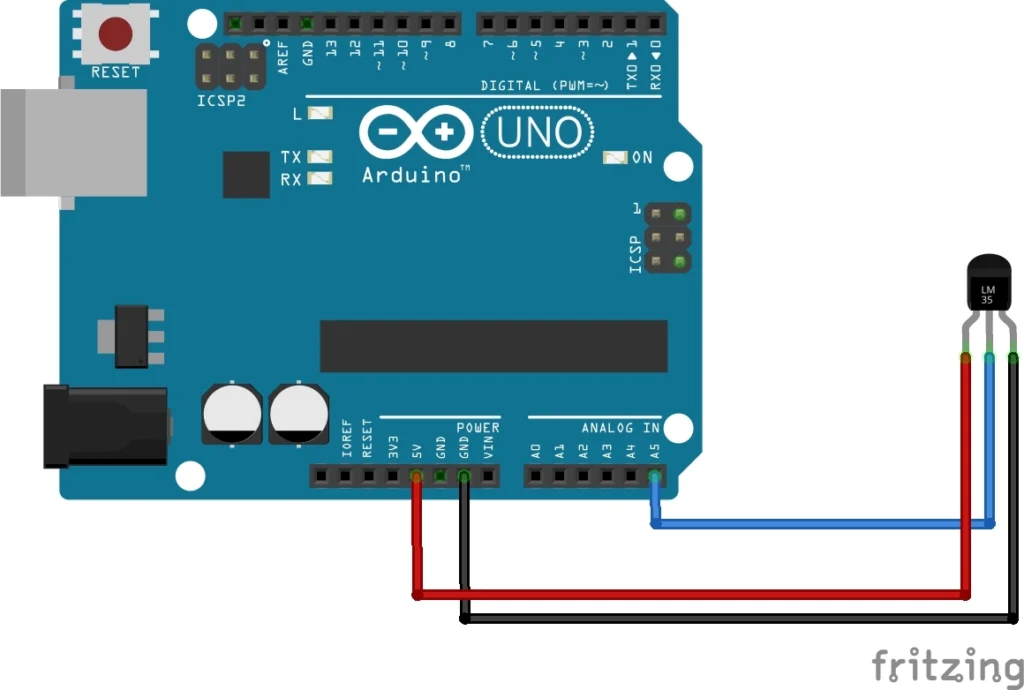
Let’s connect the LM35 temperature sensor to an Arduino to measure temperature. The LM35 outputs a voltage that varies with temperature changes, allowing us to easily read and interpret the temperature data using the Arduino.
Wiring the LM35 to Arduino
- Pin 1 (Vs): Connect to +5V on Arduino
- Pin 2 (Vout): Connect to an analog input pin on Arduino (e.g., A5)
- Pin 3 (GND): Connect to Ground (GND) on Arduino
Key Features of LM35:
- Temperature Range: -55°C to 150°C
- Output Voltage: 10 mV/°C
- Accuracy: 0.5°C +-
- operating voltage : 4 to 30v
Arduino Code
const int lm35Pin = A0; // LM35 output connected to analog pin A0
float temperature;

void setup() {
  Serial.begin(9600); // Start the Serial communication at 9600 baud rate
}

void loop() {
  // Read the analog value from LM35
  int analogValue = analogRead(lm35Pin);

  // Convert the analog value to voltage (5V reference)
  float voltage = (analogValue / 1023.0) * 5.0;

  // Convert the voltage to temperature in Celsius
  temperature = voltage * 100.0; // LM35 outputs 10mV per degree Celsius

  // Print the temperature to Serial Monitor
  Serial.print("Temperature: ");
  Serial.print(temperature);
  Serial.println(" °C");

  delay(1000); // Wait for 1 second before the next reading
}
Explanation of the Code:
- analogRead(lm35Pin): Reads the voltage output from the LM35.
- Voltage Calculation: The analog reading is converted to voltage based on the reference voltage (5V). The formula used accounts for the ADC resolution (10 bits = 1024 levels).
- Temperature Calculation: The output voltage is then converted to temperature using the LM35’s output characteristic (10 mV/°C).
- Serial Output: The temperature is printed to the Serial Monitor for real-time monitoring.
ADC Maths
To interpret the values from an LM35 temperature sensor in Arduino code, we need to understand how the sensor works, how to convert its output voltage into temperature, and how these calculations relate to the reference voltage and ADC resolution.
Understanding the LM35
The LM35 temperature sensor outputs a voltage proportional to the temperature in degrees Celsius. Specifically, it provides a linear output of 10 mV per degree Celsius. For example:
- At 0°C, the output is 0 mV.
- At 25°C, the output is 250 mV.
- At 100°C, the output is 1,000 mV (or 1 V).
The Arduino Uno’s ADC (Analog to Digital Converter) has a 10-bit resolution, meaning it can convert analog input voltages into a digital value ranging from 0 to 1023. The maximum input voltage is 5V, which corresponds to the maximum digital value of 1023.
Mathematical Interpretation
- Voltage Calculation from ADC Reading : To convert the ADC value back into voltage, we use the formula:
$$ Vin\;=\frac{ADC\;value}{1023}\times\;Vref $$
Where:
- Vin is the input voltage (output from LM35).
- ADC value is the value read from the analog pin.
- Vref is the reference voltage (typically 5V for the Arduino).
2. Temperature Calculation
Once we have Vin we can calculate the temperature in Celsius using the LM35 specification:
$$Temprature(C)\;=\frac{Vin}{10mV/C}=\;\frac{Vin}{0.01V/C}$$
Putting it together, we can substitute Vin :
$$ Temprature(C)\;=\frac{Vref\;\times\;ADC\;value}{1023\;\times\;0.01}$$
Conclusion
Analog to Digital Converters are fundamental components that enable the interaction between the analog and digital realms. As technology continues to evolve, the role of ADCs will only become more prominent, facilitating advancements across various sectors. Understanding their functionality and applications can help us appreciate the essential role they play in our increasingly digital lives. Whether it’s capturing sound in a smartphone or measuring temperature in an industrial setting, ADCs are quietly working behind the scenes, converting the analog world into a format we can understand and utilize.