
In the world of electronics, especially in digital circuits, the concepts of pull-up and pull-down resistors play a crucial role in ensuring reliable signal levels. While these components may seem simple at first glance, they serve essential functions in controlling the behavior of digital inputs. In this article, we’ll explore what pull-up and pull-down resistors are, how they work, and where they’re used.
What Are Pull-Up and Pull-Down Resistors?
Pull-Up Resistors
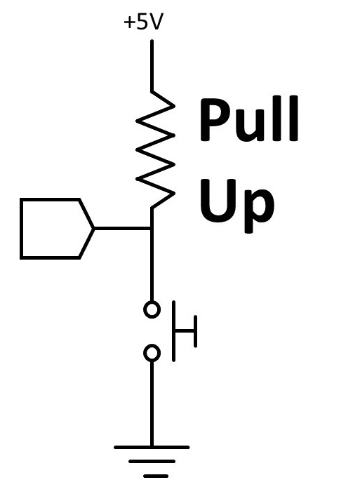
A pull-up resistor is connected between a digital input pin and a positive voltage supply (typically Vcc). Its primary function is to ensure that the input pin reads a HIGH (logic 1) state when no active device is driving the pin low. This setup prevents the pin from floating, which can lead to unpredictable behavior.
Example Application: Consider a simple push-button switch. When the button is not pressed, the pull-up resistor pulls the input pin high. When the button is pressed, it connects the pin directly to ground, driving it low (logic 0). This configuration ensures that the input pin always has a defined state.
Pull-Down Resistors
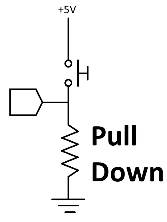
Conversely, a pull-down resistor is connected between a digital input pin and ground (0V). This arrangement guarantees that the input pin reads a LOW (logic 0) state when no active device is driving the pin high. Like pull-up resistors, pull-down resistors prevent floating states that can cause erratic circuit behavior.
Example Application: Using the same push-button switch example, if the pull-down resistor is used, the setup is inverted. When the button is not pressed, the pull-down resistor keeps the input pin low. When pressed, the button connects the pin to Vcc, driving it high.
Why Use Pull-Up and Pull-Down Resistors?
- Preventing Floating Inputs: In digital circuits, an unconnected input pin can float between HIGH and LOW states due to noise, leading to unpredictable behavior. Pull-up and pull-down resistors ensure that there’s always a defined logic level.
- Simplifying Circuit Design: By using these resistors, designers can simplify circuit designs. They eliminate the need for additional logic components just to maintain a defined input state.
- Improving Noise Immunity: Pull-up and pull-down resistors help improve the noise immunity of digital circuits. By providing a strong connection to either Vcc or ground, they minimize the effects of electromagnetic interference (EMI).
Selecting the Right Resistor Value
Choosing the appropriate resistor value for pull-up or pull-down configurations is crucial for circuit performance. Typical values range from 1kΩ to 10kΩ, but the optimal value depends on several factors, including:
- Input Impedance: The input impedance of the connected device should be taken into account. A lower resistor value can provide a stronger pull but may increase current consumption.
- Current Requirements: Ensure that the chosen resistor value doesn’t allow excessive current to flow when the input is actively driven.
- Speed of Signal: In high-speed applications, a lower resistance value may be necessary to achieve faster signal transitions.
Practical Applications
Pull-up and pull-down resistors are widely used in various applications, including:
- Microcontroller Interfaces: Most microcontrollers require pull-up or pull-down resistors for digital inputs, particularly for buttons, switches, and sensors.
- I2C Communication: In I2C communication, pull-up resistors are used on the SDA and SCL lines to ensure reliable communication.
- Logic Gates: In circuits involving logic gates, these resistors can help maintain stable input states.
Conclusion
Pull-up and pull-down resistors are fundamental components in digital electronics that ensure reliable operation and signal integrity. By understanding how to implement and utilize these resistors effectively, you can design robust circuits that perform reliably under varying conditions. Whether you’re working on a simple hobby project or a complex embedded system, mastering these concepts is essential for any aspiring electronics engineer.