
In a world where convenience and automation reign supreme, the ability to control our devices seamlessly has become essential. Imagine this: you have an old television remote that you can’t find, or perhaps you want to consolidate multiple remotes into one streamlined controller for your home theater setup. Cloning an IR remote using an Arduino can provide a practical solution to these everyday challenges. By capturing the signals of your existing remote, you can easily replicate its functions, allowing you to control your devices without the hassle of searching for lost remotes or dealing with clutter. In this article, we’ll guide you through the process of cloning an IR remote control with Arduino, showcasing how you can enhance your home automation experience with a simple DIY project.
Understanding IR Communication
Infrared communication relies on modulated light waves to transmit data between devices. An IR remote control typically sends a series of pulses (on and off signals) that represent binary data. To clone a remote, we need to capture these pulses and then replicate them.
What You’ll Need
For this we will need
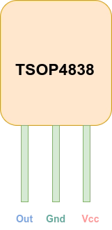
- Infrared Receivers which can receive ir signal (e.g. TSOP4838)
- Micro-controller which can decode this ir signal. In this case we are using Arduino nano.
- A software library which helps us in decoding the signal (which can be found here :
Wiring the Components
- Connect the VCC pin of the IR receiver to the 5V pin on the Arduino.
- Connect the GND pin to the GND on the Arduino.
- Connect the OUT pin to a digital pin 2 on the Arduino
Installing library : To install the library open Arduino , then open Library manager and search for “IRremote” and install it .
Coding
So the first step is to get the the ir codes of the target remote when a specific button is pressed .
To do this open the “ReceiverDump” example code IRremote library which should look like this :
#include <Arduino.h>

#include "PinDefinitionsAndMore.h" // Define macros for input and output pin etc.

#if !defined(RAW_BUFFER_LENGTH)
// For air condition remotes it requires 750. Default is 200.
#  if !((defined(RAMEND) && RAMEND <= 0x4FF) || (defined(RAMSIZE) && RAMSIZE < 0x4FF))
#define RAW_BUFFER_LENGTH  730 // this allows usage of 16 bit raw buffer, for RECORD_GAP_MICROS > 20000
#  endif
#endif

/*
 * MARK_EXCESS_MICROS is subtracted from all marks and added to all spaces before decoding,
 * to compensate for the signal forming of different IR receiver modules. See also IRremote.hpp line 142.
 *
 * You can change this value accordingly to the receiver module you use.
 * The required value can be derived from the timings printed here.
 * Keep in mind that the timings may change with the distance
 * between sender and receiver as well as with the ambient light intensity.
 */
#define MARK_EXCESS_MICROS    20    // Adapt it to your IR receiver module. 20 is recommended for the cheap VS1838 modules.

//#define RECORD_GAP_MICROS 12000 // Default is 8000. Activate it for some LG air conditioner protocols
//#define DEBUG // Activate this for lots of lovely debug output from the decoders.

#include <IRremote.hpp>

//+=============================================================================
// Configure the Arduino
//
void setup() {
    pinMode(LED_BUILTIN, OUTPUT);

    Serial.begin(115200);   // Status message will be sent to PC at 9600 baud
    while (!Serial)
        ; // Wait for Serial to become available. Is optimized away for some cores.

#if defined(__AVR_ATmega32U4__) || defined(SERIAL_PORT_USBVIRTUAL) || defined(SERIAL_USB) /*stm32duino*/|| defined(USBCON) /*STM32_stm32*/ \
    || defined(SERIALUSB_PID)  || defined(ARDUINO_ARCH_RP2040) || defined(ARDUINO_attiny3217)
    delay(4000); // To be able to connect Serial monitor after reset or power up and before first print out. Do not wait for an attached Serial Monitor!
#endif
    // Just to know which program is running on my Arduino
    Serial.println(F("START " __FILE__ " from " __DATE__ "\r\nUsing library version " VERSION_IRREMOTE));

    // Start the receiver and if not 3. parameter specified, take LED_BUILTIN pin from the internal boards definition as default feedback LED
    IrReceiver.begin(IR_RECEIVE_PIN, ENABLE_LED_FEEDBACK);

    Serial.print(F("Ready to receive IR signals of protocols: "));
    printActiveIRProtocols(&Serial);
    Serial.println(F("at pin " STR(IR_RECEIVE_PIN)));

    // infos for receive
    Serial.print(RECORD_GAP_MICROS);
    Serial.println(F(" us is the (minimum) gap, after which the start of a new IR packet is assumed"));
    Serial.print(MARK_EXCESS_MICROS);
    Serial.println();
    Serial.println(F("Because of the verbose output (>200 ms at 115200 baud), repeats are not dumped correctly!"));
    Serial.println();
    Serial.println(
            F(
                    "If you receive protocol NEC, Samsung or LG, run also ReceiveDemo to check if your actual protocol is eventually NEC2 or SamsungLG, which is determined by the repeats"));
    Serial.println();

}

//+=============================================================================
// The repeating section of the code
//
void loop() {
    if (IrReceiver.decode()) {  // Grab an IR code
        // At 115200 baud, printing takes 200 ms for NEC protocol and 70 ms for NEC repeat
        Serial.println(); // blank line between entries
        Serial.println(); // 2 blank lines between entries
        IrReceiver.printIRResultShort(&Serial);
        // Check if the buffer overflowed
        if (IrReceiver.decodedIRData.flags & IRDATA_FLAGS_WAS_OVERFLOW) {
            Serial.println(F("Try to increase the \"RAW_BUFFER_LENGTH\" value of " STR(RAW_BUFFER_LENGTH) " in " __FILE__));
            // see also https://github.com/Arduino-IRremote/Arduino-IRremote#compile-options--macros-for-this-library
        } else {
            if (IrReceiver.decodedIRData.protocol == UNKNOWN) {
                Serial.println(F("Received noise or an unknown (or not yet enabled) protocol"));
            }
            Serial.println();
            IrReceiver.printIRSendUsage(&Serial);
            Serial.println();
            Serial.println(F("Raw result in internal ticks (50 us) - with leading gap"));
            IrReceiver.printIRResultRawFormatted(&Serial, false); // Output the results in RAW format
            Serial.println(F("Raw result in microseconds - with leading gap"));
            IrReceiver.printIRResultRawFormatted(&Serial, true);  // Output the results in RAW format
            Serial.println();                               // blank line between entries
            Serial.print(F("Result as internal 8bit ticks (50 us) array - compensated with MARK_EXCESS_MICROS="));
            Serial.println(MARK_EXCESS_MICROS);
            IrReceiver.compensateAndPrintIRResultAsCArray(&Serial, false); // Output the results as uint8_t source code array of ticks
            Serial.print(F("Result as microseconds array - compensated with MARK_EXCESS_MICROS="));
            Serial.println(MARK_EXCESS_MICROS);
            IrReceiver.compensateAndPrintIRResultAsCArray(&Serial, true); // Output the results as uint16_t source code array of micros
            IrReceiver.printIRResultAsCVariables(&Serial);  // Output address and data as source code variables
            Serial.println();                               // blank line between entries

            IrReceiver.compensateAndPrintIRResultAsPronto(&Serial);

            /*
             * Example for using the compensateAndStorePronto() function.
             * Creating this String requires 2210 bytes program memory and 10 bytes RAM for the String class.
             * The String object itself requires additional 440 bytes RAM from the heap.
             * This values are for an Arduino Uno.
             */
//        Serial.println();                                     // blank line between entries
//        String ProntoHEX = F("Pronto HEX contains: ");        // Assign string to ProtoHex string object
//        if (int size = IrReceiver.compensateAndStorePronto(&ProntoHEX)) {   // Dump the content of the IReceiver Pronto HEX to the String object
//            // Append compensateAndStorePronto() size information to the String object (requires 50 bytes heap)
//            ProntoHEX += F("\r\nProntoHEX is ");              // Add codes size information to the String object
//            ProntoHEX += size;
//            ProntoHEX += F(" characters long and contains "); // Add codes count information to the String object
//            ProntoHEX += size / 5;
//            ProntoHEX += F(" codes");
//            Serial.println(ProntoHEX.c_str());                // Print to the serial console the whole String object
//            Serial.println();                                 // blank line between entries
//        }
        }
        IrReceiver.resume();                            // Prepare for the next IR frame
    }
}
if you do not change anything in the code then here is the default pin mapping in the library :
/*
 * Pin mapping table for different platforms
 *
 * Platform     IR input    IR output   Tone      Core/Pin schema
 * --------------------------------------------------------------
 * DEFAULT/AVR  2           3           4         Arduino
 * ATtinyX5     0|PB0       4|PB4       3|PB3     ATTinyCore
 * ATtiny167    3|PA3       2|PA2       7|PA7     ATTinyCore
 * ATtiny167    9|PA3       8|PA2       5|PA7     Digispark original core
 * ATtiny84      |PB2        |PA4        |PA3     ATTinyCore
 * ATtiny88     3|PD3       4|PD4       9|PB1     ATTinyCore
 * ATtiny3217  18|PA1      19|PA2      20|PA3     MegaTinyCore
 * ATtiny1604   2           3|PA5       %
 * ATtiny816   14|PA1      16|PA3       1|PA5     MegaTinyCore
 * ATtiny1614   8|PA1      10|PA3       1|PA5     MegaTinyCore
 * SAMD21       3           4           5
 * ESP8266      14|D5       12|D6       %
 * ESP32        15          4          27
 * ESP32-C3     2           3           4
 * BluePill     PA6         PA7       PA3
 * APOLLO3      11          12          5
 * RP2040       3|GPIO15    4|GPIO16    5|GPIO17
*/Since we are using an Arduino Nano, which is based on the AVR architecture, the input pin is set to 2.
Getting the Ir codes
- To get the codes run the above code and press any button .
- On you serial monitor you will see bunch of stuff but we are only interested in “address and command” .
- Note down this values for each button press . We will use these values latter .
Making Ir remote
Now that we have ir codes we can start building the ir remote clone.
What You’ll Need
To make a IR remote you will need :
- Ir led
- Arudino and same IRremote library that we have seen previously.
Circuit Connection :
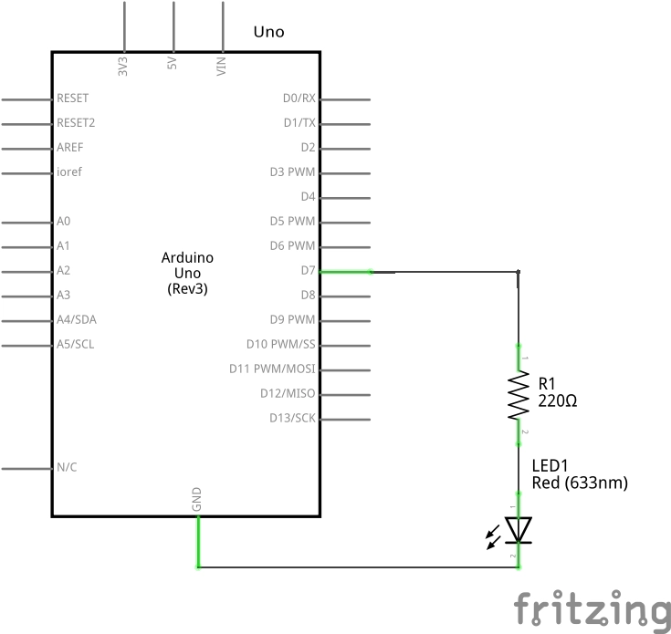
To test this we can send the commands on Uart of Arduino and based on the these commands we can send the IR codes that we have recorded in the previous step.
#include <IRremote.h>

const int irLedPin = 7;
//const int irLedPin = 6;

IRsend irsend(irLedPin);

uint16_t address = 0x0;

// Remote for led rgb bulb
uint16_t off = 0x1F;
uint16_t on = 0xD;
uint16_t incBrt = 0x9;
uint16_t decBrt = 0x1D;

uint16_t red = 0x19;
uint16_t redL = 0x17;
uint16_t orange = 0x40;
uint16_t orangeL = 0xA;
uint16_t yellow = 0x1C;

uint16_t green = 0x1B;
uint16_t greenL = 0x12;
uint16_t blue = 0x4C;
uint16_t cyan = 0x1E;
uint16_t navyBlue = 0x14;

uint16_t royalblue = 0x11;
uint16_t otherblue = 0x16;
uint16_t purple = 0x4;
uint16_t purpleL = 0xE;
uint16_t pink = 0xF;

uint16_t white = 0x15;
uint16_t flash = 0x4D;
uint16_t strobe = 0x0;
uint16_t fade = 0x1A;
uint16_t smooth = 0xC;

void setup() {
  Serial.begin(115200);  // Start serial communication at 9600 baud rate
}

void loop() {
  if (Serial.available()) {
    String command = Serial.readStringUntil('\n');  // Read serial input until newline character

    // Convert command to lower case for easier comparison
    command.toLowerCase();

    // Check the command and send the corresponding IR signal
    uint16_t code = 0xFFFF;  // Default to an invalid code

    if (command == "red") {
      code = red;
    } else if (command == "blue") {
      code = blue;
    } else if (command == "on") {
      code = on;
    } else if (command == "off") {
      code = off;
    } else if (command == "green") {
      code = green;
    } else if (command == "incbrt") {
      code = incBrt;
    } else if (command == "decbrt") {
      code = decBrt;
    } else if (command == "redl") {
      code = redL;
    } else if (command == "orange") {
      code = orange;
    } else if (command == "orangel") {
      code = orangeL;
    } else if (command == "yellow") {
      code = yellow;
    } else if (command == "cyan") {
      code = cyan;
    } else if (command == "navyblue") {
      code = navyBlue;
    } else if (command == "royalblue") {
      code = royalblue;
    } else if (command == "otherblue") {
      code = otherblue;
    } else if (command == "purple") {
      code = purple;
    } else if (command == "purplel") {
      code = purpleL;
    } else if (command == "pink") {
      code = pink;
    } else if (command == "white") {
      code = white;
    } else if (command == "flash") {
      code = flash;
    } else if (command == "strobe") {
      code = strobe;
    } else if (command == "fade") {
      code = fade;
    } else if (command == "smooth") {
      code = smooth;
    } else {
      Serial.println("Unknown command: " + command);  // Optionally print unknown commands
      return;
    }

    irsend.sendNEC(address, code,   1);
    Serial.print("Received command: ");
    Serial.println(command);

    delay(500);  // Wait for a short period to avoid sending signals too quickly
  }
}
Explanation :
- In this i am sending the commands using the Raspberry pi which is running python script (you can use other Arduino or any other Mcu) .
- if the command matches then we send predefined Ir code [Note : we recorded these codes form the previous step).
Conclusion
Congratulations! You’ve successfully cloned an IR remote control using Arduino. This project not only enhances your understanding of IR communication but also opens the door to creating custom remotes for various applications. From controlling home appliances to building interactive projects, the possibilities are endless.
Additional Ideas
- Create a universal remote that can control multiple devices.
- Integrate with a web server to control devices over the internet.
- Combine with other sensors for more interactive projects.
Feel free to experiment, modify, and extend this project to suit your needs. Happy tinkering!