

State machines are fundamental models used in computer science and engineering to describe the behavior of systems. They provide a structured way to represent states and transitions, making it easier to design and manage complex systems. In this article, we’ll explore what state machines are, their types, applications, and how to implement them.
What is a State Machine?
A state machine is a computational model that outlines how a system behaves in various states based on inputs. It consists of a defined set of states, transitions between those states, and events that trigger those transitions. This model is particularly useful in programming for managing complex system behaviours clearly and efficiently.
Key Components of State Machines
When creating a state machine in C, you’ll typically deal with:
- States: The various conditions or modes the system can be in.
- Transitions: Rules dictating how the system moves from one state to another based on inputs.
- Events: Inputs that trigger state transitions, like user actions or system signals.
- Actions: Functions executed during state transitions or when entering/exiting states.
- Initial State: The starting condition of the state machine.
- Final State: An optional state marking the end of operations.
Types of State Machines
- Finite State Machine (FSM): An FSM has a limited number of states and is straightforward to implement using switch-case structures in C.
- Mealy Machine: In a Mealy machine, outputs depend on the current state and the input, providing responsive behaviour within the transition logic.
- Moore Machine: A Moore machine produces outputs based solely on its current state, simplifying output management.
- Hierarchical State Machine: This type allows states to contain other states, helping to manage complex behaviours effectively.
Applications of State Machines
State machines are widely used in various fields, including:
- Embedded Systems: Managing states in devices like washing machines, microwaves, and other appliances.
- User Interface Design: Controlling the state of user interactions, such as navigating through menus or forms.
- Protocol Design: Managing the states of communication protocols, ensuring correct sequencing and error handling.
- Game Development: Controlling game character behaviors, including state transitions for actions like walking, running, and jumping.
- Workflow Management: Representing complex workflows in software applications, automating transitions based on user inputs or conditions.
Implementing a Simple State Machine in Arduino Ide
Here’s a practical example of a finite state machine (FSM) in Arduino. This example will use an LED and a button to demonstrate how the FSM can manage different states, allowing the LED to blink, turn on, or turn off based on button presses
Hardware Required
- Arduino board (e.g., Arduino Uno)
- LED
- 220-ohm resistor
- Push button
- 10k-ohm resistor (for the button pull-down)
- Breadboard and jumper wires
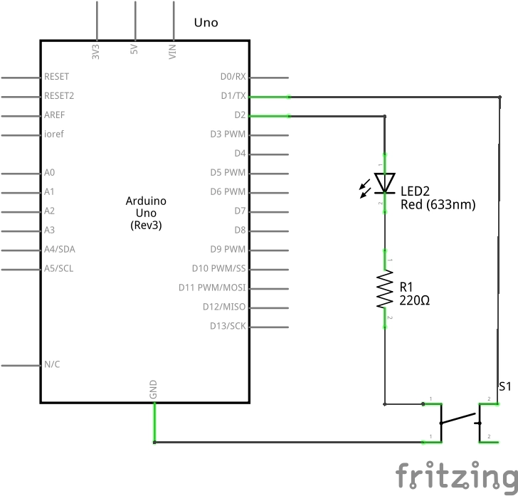
Circuit Connections
- Connect the LED:
- Anode (long leg) to a digital pin (e.g., pin 2) through a 220-ohm resistor.
- Cathode (short leg) to GND
- Connect the push button:
- One terminal to a digital pin (e.g., pin 1).
- The other terminal to GND.
Arduino Code
// Define states
enum State {
    OFF,
    ON,
    BLINK
};
State currentState = OFF; // Start in the OFF state
// Pin definitions
const int ledPin = 2;
const int buttonPin = 1;
// Timing variables
unsigned long previousMillis = 0;
const long blinkInterval = 500; // Blink interval in milliseconds
void setup() {
    pinMode(ledPin, OUTPUT);
    pinMode(buttonPin, INPUT_PULLUP);
    Serial.begin(9600);
}
void loop() {
    switch (currentState) {
        case OFF:
            digitalWrite(ledPin, LOW); // LED is OFF
            checkButton();
            break;
        case ON:
            digitalWrite(ledPin, HIGH); // LED is ON
            checkButton();
            break;
        case BLINK:
            unsigned long currentMillis = millis();
            if (currentMillis - previousMillis >= blinkInterval) {
                previousMillis = currentMillis;
                // Toggle LED state
                digitalWrite(ledPin, !digitalRead(ledPin));
            }
            checkButton();
            break;
    }
}
void checkButton() {
    // Check button press
    if (digitalRead(buttonPin) == HIGH) {
        delay(50); // Simple debounce
        if (digitalRead(buttonPin) == HIGH) { // Confirm button press
            switch (currentState) {
                case OFF:
                    currentState = ON; // Transition to ON state
                    Serial.println("LED ON");
                    break;
                case ON:
                    currentState = BLINK; // Transition to BLINK state
                    Serial.println("LED BLINKING");
                    break;
                case BLINK:
                    currentState = OFF; // Transition to OFF state
                    digitalWrite(ledPin, LOW); // Ensure LED is OFF
                    Serial.println("LED OFF");
                    break;
            }
        }
    }
}
Running the code
- Upload the code to your Arduino.
- Press the button to change the LED state:
- Press once: Turns the LED ON.
- Press again: Starts blinking the LED.
- Press again: Turns the LED OFF.
Conclusion
This example demonstrates how to implement a finite state machine in Arduino . This can be further extended to mimic thread-like functionality by changing the currentState variable based on some event or interrupt. By managing states based on button presses, you can control an LED in different ways without blocking the main loop, similar to how threads would operate in more complex environments.